What the Image Shows
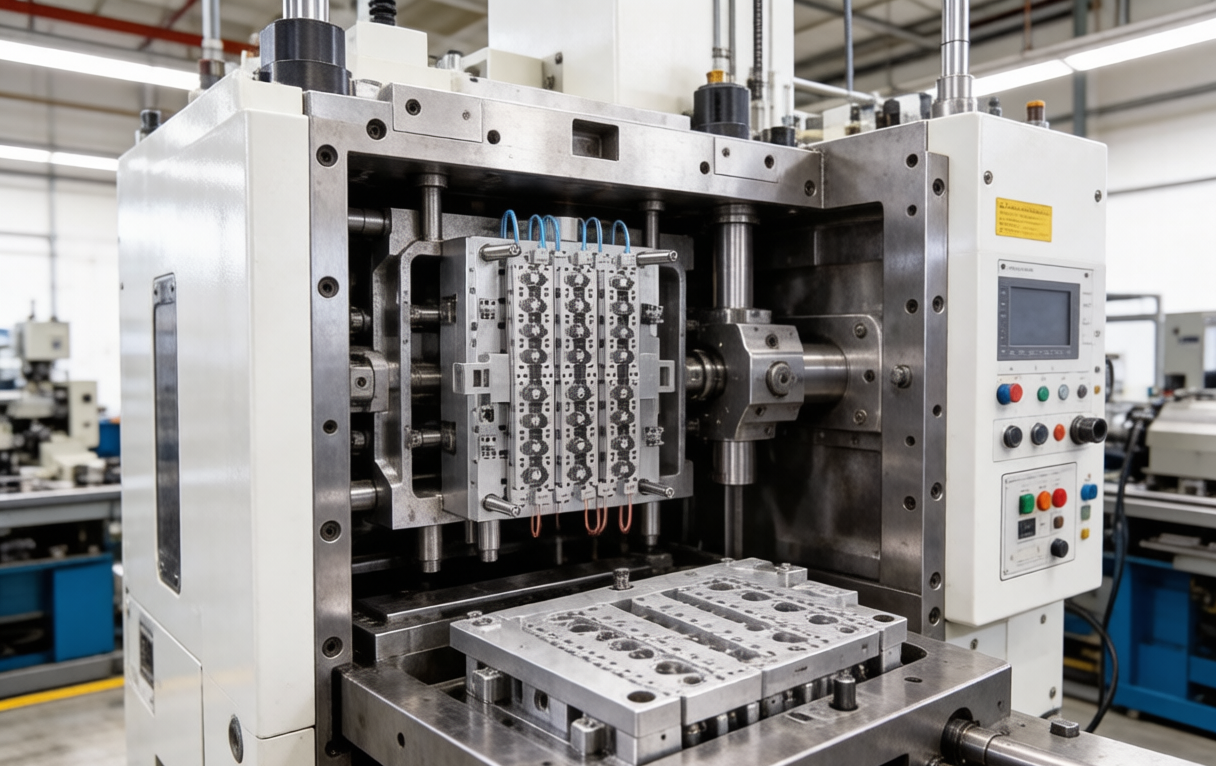
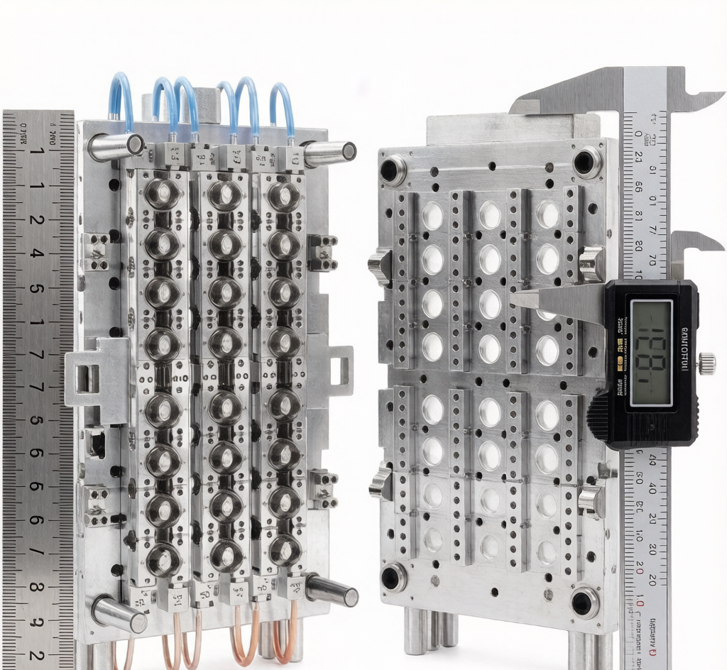
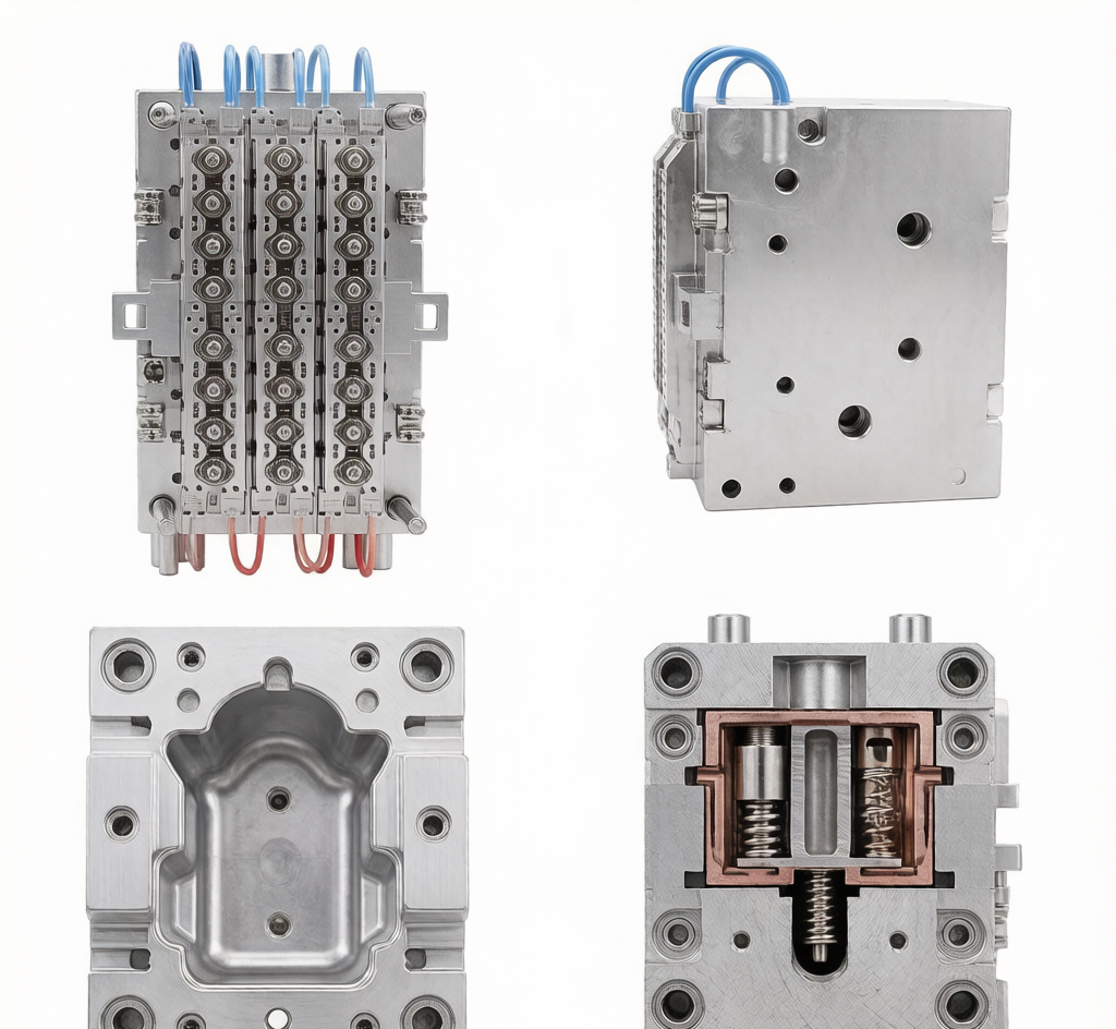
The photograph captures a multi-cavity outer cap mold mounted inside an injection molding machine. In the center is the cavity block with a dense, grid-style arrangement of cap impressions; blue flexible tubes deliver cooling water to each cavity zone, while hardened guide pillars and locking wedges align the moving and stationary halves. A touchscreen control panel is visible on the right, indicating that this is a production-ready setup rather than a bench photograph.
Why Cavity Layout Matters in Cap Molds
For cosmetic and household packaging closures, the outer cap (shell) must present uniform wall thickness, clean parting lines and consistent thread or snap-fit geometry. A multi-cavity layout lets brand owners hit high-volume targets, but it also multiplies any small imbalance:
- Flow imbalance between cavities causes weight variation and dimensional drift.
- Thermal gradients across the mold face lead to warpage or sink marks.
- Stack height mismatch between cavity and core inserts creates flash or under-fill.
Engineers typically pair cavity layout design with mold-flow analysis before steel is cut, verifying that the runner system fills every impression at similar pressure and temperature.
Cooling Circuit Design for Cycle Time and Part Quality
The blue cooling lines in the image are not merely plumbing — they determine cycle time and cosmetic appearance. In cap molding, rapid and even cooling preserves surface gloss and prevents ovality. Best practices include:
- Conformal cooling channels that follow cavity contours when geometry allows.
- Parallel circuits with balanced flow rates, avoiding short-circuiting.
- Separate temperature zones for core and cavity when different shrinkage behavior is expected.
- Strategic baffle or bubbler inserts in deep rib or thread areas.
A well-cooled outer cap mold can often reduce cycle time by 10–20 % compared with a poorly cooled counterpart, directly affecting piece-part cost.
Mold-to-Machine Interface and Alignment
The image also highlights the mechanical interface: locating rings, guide pins, clamping rails and ejector connections must match the molding machine specification. For a precision cap mold, repeatability depends on:
- Guide pillar alignment and wear condition.
- Platen parallelism under clamp tonnage.
- Ejector stroke synchronization to avoid skewed part release.
- Hot-runner or cold-runner compatibility with the machine nozzle geometry.
These details are especially important when the same mold is expected to run across several machines on a factory floor.
Materials and Manufacturing Notes
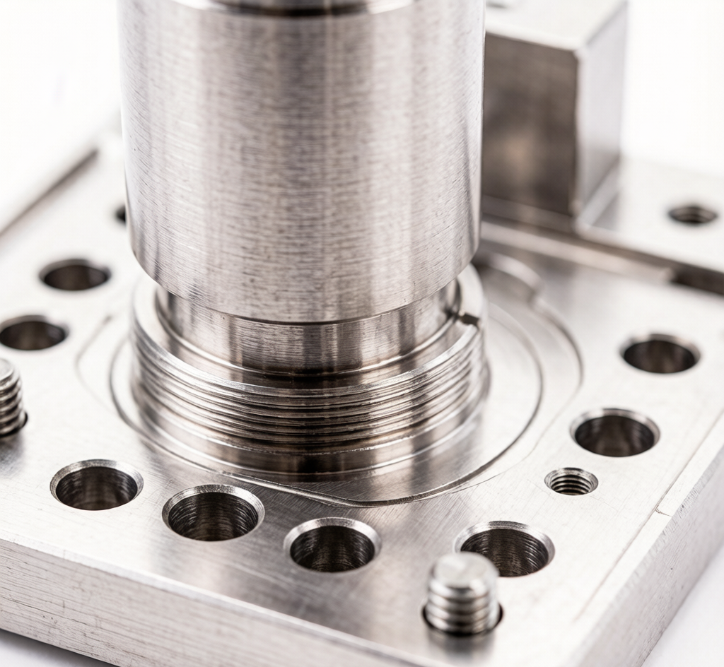
Outer cap molds for daily-chemical and cosmetic packaging commonly use pre-hardened steels such as P20/718H for the mold base and cavity inserts, with S136/420SS or NAK80 chosen when mirror finish or corrosion resistance is required. Core pins, thread rings and sliding inserts often receive vacuum heat treatment or surface hardening to extend service life against abrasive resin fillers.
SHENGQI Precision Support
Dongguan Shengqi Precision Mould Components Co., Ltd. supplies custom cavity inserts, core pins, thread rings and full mold component sets for cap and closure molds. With 21+ years of experience, two production bases totaling 40,000 m², 330+ machining centers and ISO 9001:2015 / ISO 13485 / ISO 14001 certifications, SHENGQI delivers DFM support, mold-flow consultation and precision machining for multi-cavity packaging molds. Contact Jason Wong: +86 13652919880, jasonwong@shengqi.com, www.dgshengqi.com.