Why a Large Ejector Sleeve Is a Hidden Reliability Lever
In any high-cavity mould running thin-wall packaging, dairy caps, PET preforms, or large consumer-container tools, the ejector sleeve (Chinese: 大推套, also known as 司筒 or ejector bushing) is one of the most under-discussed wear parts. Once the bore diameter pushes past ~80 mm and the demoulding stroke climbs above 30 mm, the sleeve stops being a commodity bushing and starts behaving as a structural component that defines mould uptime, flash rate, part cosmetics and operator safety. For mould builders sourcing these sleeves for the first time, the difference between a sleeve that lasts 1 million shots and one that fails at 200k almost always traces back to design and heat-treatment decisions made on paper.
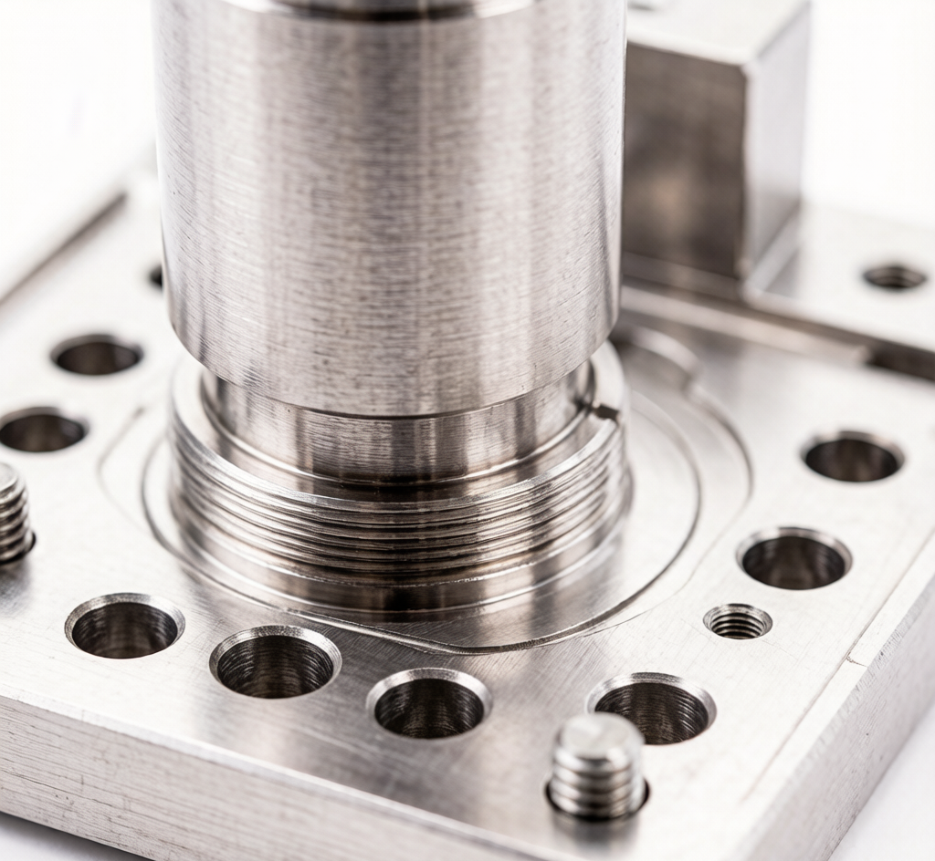
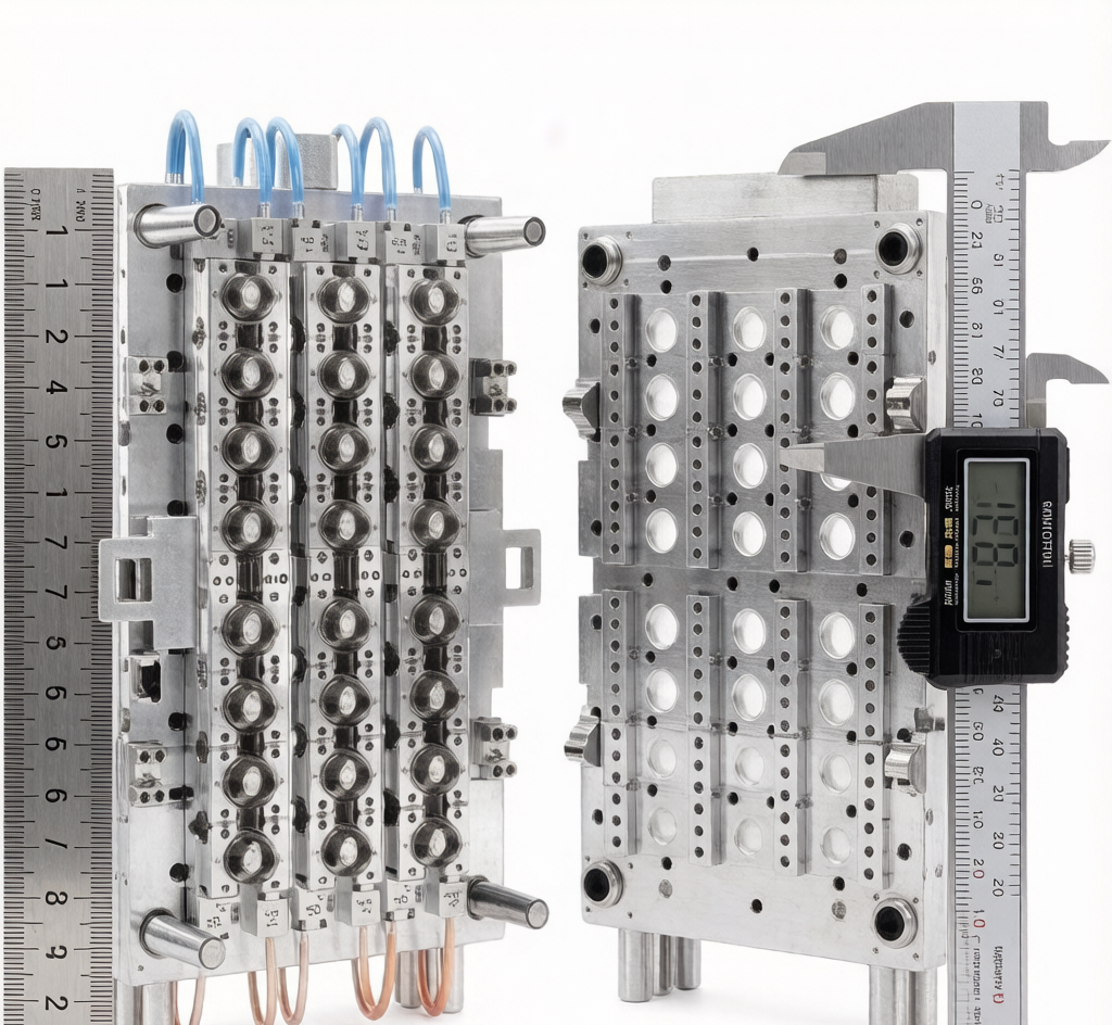
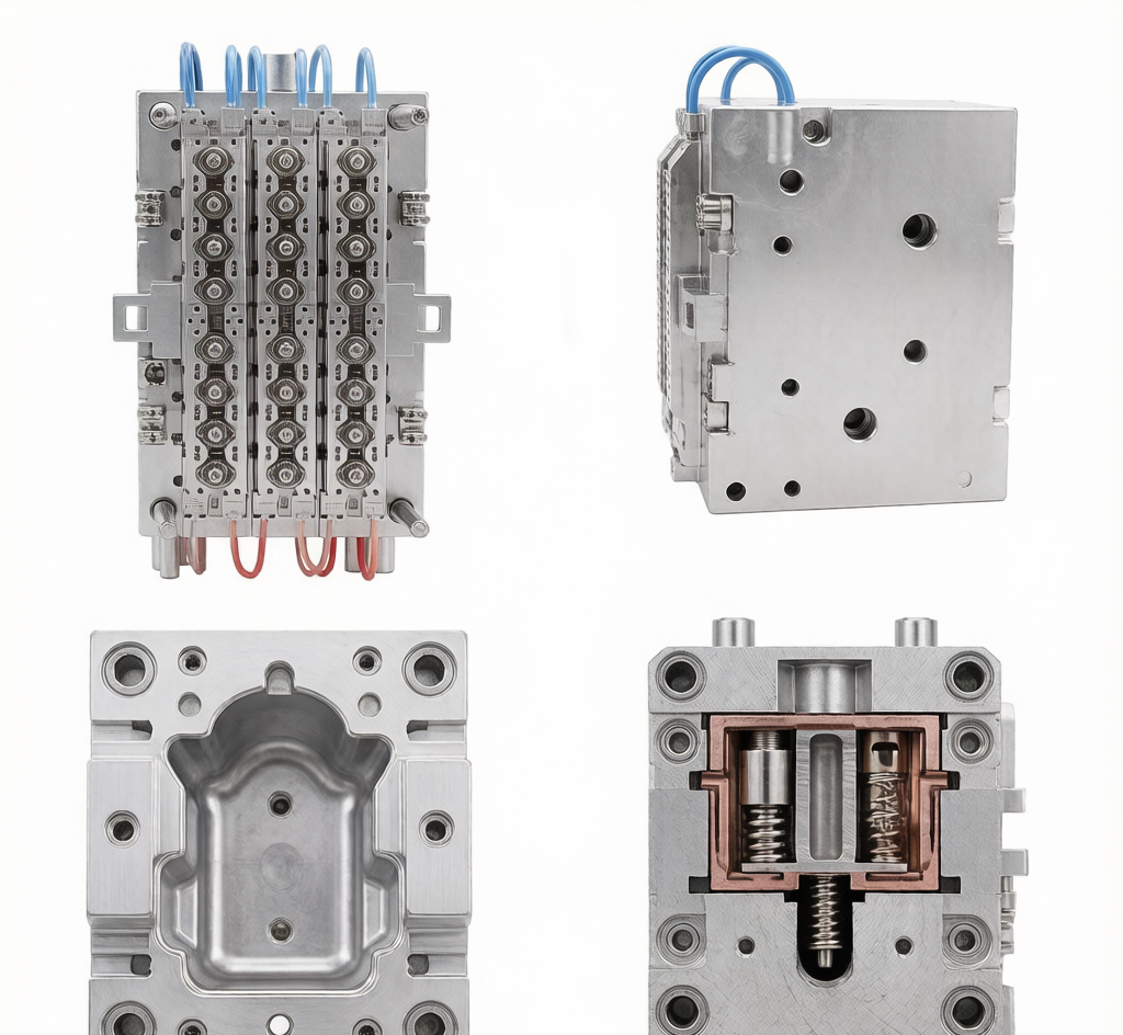
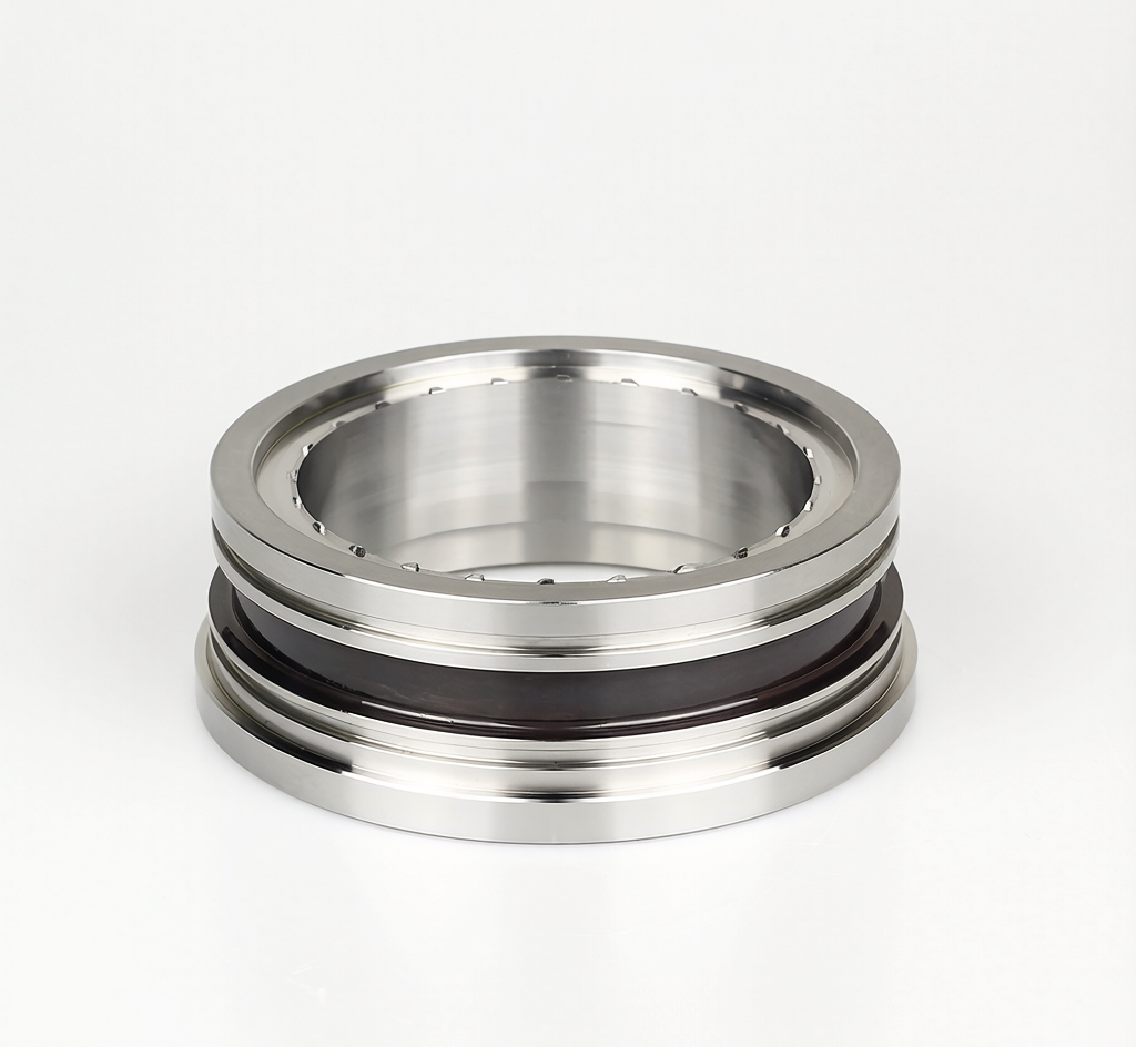
The unit pictured is a large-diameter stepped ejector sleeve from a SHENGQI production batch — a mirror-finish stainless assembly with a top flange, a polished inner bore containing small peripheral features, a centre sealing band, and a symmetric bottom flange. Each of those features exists for a specific engineering reason, and this review unpacks them one by one for procurement, mould-design and quality teams.
Who this article is for: mould designers evaluating ejector systems for high-cavity packaging tools; sourcing managers comparing precision mould components suppliers; and quality engineers who need a tolerance checklist they can hand to incoming-inspection. The terminology used follows MISUMI / DME / HASCO conventions so it maps cleanly to your existing drawings.
1. Anatomy: What the Photograph Is Telling You
- Top and bottom flanges (镜面法兰): provide the shoulder seats that register the sleeve inside the mould base and the support plate. Concentricity of these flanges to the bore is what keeps the sleeve coaxial with the cavity — without it, the demoulding force walks sideways and you get wall-thickness drift on every shot.
- Polished inner bore (内孔镜面): the surface that actually contacts the plasticised part. A bore roughness of Ra ≤ 0.05 µm is the working baseline for visible-surface packaging; anything rougher shows up as streaks on the first 50–100 shots.
- Small peripheral features (内圈小孔): these are either vacuum-breaker ports, ejector-pin clearances, or coolant cross-drills depending on the mould architecture. Each one is a potential leak path if the geometry is sloppy, which is why they are drilled and reamed individually rather than punched.
- Centre sealing band (中部密封圈位): the dark band is an elastomer retainer groove, typically NBR or FKM. On large-bore sleeves the band serves three functions — vacuum retention for gas-assist moulding, oil retention for self-lubrication, and a thermal buffer that reduces bore distortion under cycling temperatures.
2. Why Large Bore Diameters Break the Textbook
Standard ejector sleeves in the 6–25 mm range follow textbook design rules with very few caveats. Above ~50 mm bore, three things break the textbook and the supplier who quotes the cheapest bushing is almost never the supplier who has dealt with them:
- Buckling under ejector force. The Euler load on a thin-wall sleeve drops rapidly with length, so the wall profile has to be stepped (as you see in this unit) to add local stiffness exactly where the demoulding load is highest. A constant wall-thickness sleeve in this size will deflect visibly after a few thousand strokes.
- Bore ovality from heat-treatment distortion. Larger cross-sections quench unevenly, so a single tempering pass is rarely enough — vacuum heat treatment with at least two tempers is the working baseline for any bore above 60 mm. Air-furnace treatments will round badly and the distortion will not grind out.
- Surface distortion during ID grinding. Heat-input from grinding can re-distort a sleeve that was perfectly round after heat treatment. The cure is a stress-relief temper between rough and finish grind, plus a final hand-lapping pass on the critical 30–50 mm near the mouth where the part first releases.
3. Material and Heat-Treatment Strategy
For most large ejector sleeves, SHENGQI selects from three working families:
- SKD61 (H13 equivalent) for hot-runner-adjacent duty where the sleeve sees thermal cycling above 200 °C.
- DC53 for cold-side high-wear applications where abrasive glass-filled resins are processed.
- SUS 420J2 / S136 when the moulded part must avoid any steel contamination — medical, food-contact, or transparent packaging.
Hardness is targeted to 58–62 HRC on the working bore, with the flange faces deliberately held at 50–55 HRC so they do not chip under the clamping loads seen during mould assembly. The dual-hardness profile is not negotiable: a sleeve that is hardened uniformly to 60 HRC across the flange will chip on the third or fourth mould set-up.
Surface treatments are layered rather than single-pass:
- Vacuum heat treatment prevents oxide scale and decarburisation on the bore, which would otherwise have to be ground away — wasting precision and concentricity budget.
- Stress-relief between rough and finish grinding removes grinding-induced residual stress before the final pass.
- Optional nitriding (氮化) or DLC coating pushes surface hardness above 1000 HV for abrasive-glass-filled resins or for cycle-time-critical production.
- Mirror polishing is applied to the bore only — flanges and outer diameters are left at Ra ≤ 0.4 µm to keep them dimensionally stable under clamping.
4. Manufacturing Workflow at SHENGQI
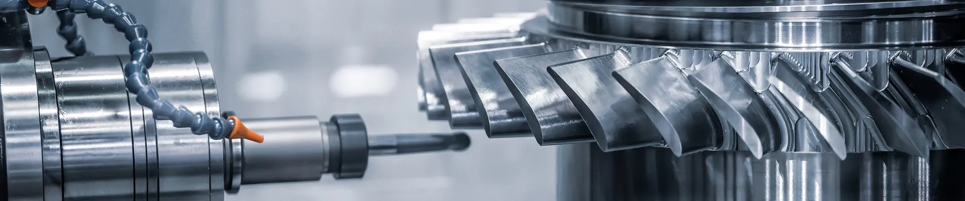
- Rough turning from pre-hardened bar stock on a CNC lathe (Doosan / Takisawa line), leaving 1.5–2 mm on all critical surfaces for finish stock.
- Deep-hole drilling on a gun-drilling machine for bores deeper than 8×D — this is the step where most suppliers fail, because drill wander becomes visible as bore eccentricity on the finished part.
- Stress-relief tempering at 580–620 °C to undo the heat-input from drilling before any further material removal.
- Vacuum heat treatment with double temper to target hardness while keeping distortion under 0.01 mm on the bore.
- ID grinding in two passes — rough at 0.05 mm/rev, finish at 0.005 mm/rev — with a final hand-lap if the bore is destined for a visible-surface mould.
- EDM for the peripheral ports and the sealing-band groove, then a light hand-polish to remove the recast layer.
- Full inspection on a ZEISS CMM for flange concentricity, a Mitutoyo roundness / cylindricity tester for the bore, and a MarSurf roughness tester for surface finish verification.
5. Tolerance Targets Worth Negotiating With Your Supplier
| Parameter | Typical tolerance | Why it matters |
|---|---|---|
| Bore diameter | ±0.005 mm | Directly controls wall-thickness drift on the moulded part. |
| Bore cylindricity | ≤ 0.003 mm | Affects demoulding force consistency shot-to-shot. |
| Flange concentricity to bore | ≤ 0.005 mm | Prevents side-loading on the ejector pin. |
| Surface roughness (bore) | Ra ≤ 0.05 µm | Visible-surface packaging requirement. |
| Sealing-band groove width | +0.00 / −0.02 mm | Holds the elastomer without compressing it to failure. |
| Overall length | ±0.02 mm | Affects stack-up with the ejector plate. |
6. Failure Modes We See in the Field
- Bore scoring: usually from glass-filled resin combined with inadequate lubrication. Mitigation — switch to DLC-coated bore, or add an oil-impregnated bronze bushing on the support plate.
- Flange chipping: from over-clamping during mould assembly. Mitigation — specify a flange hardness 4–6 HRC below the bore hardness, as noted above.
- Sealing-band groove cracking: from elastomer swelling under sustained heat. Mitigation — switch from NBR to FKM (Viton-class) elastomer, or specify a wider groove with a lower compression ratio.
- Bore ovality after 200k shots: classic heat-fatigue symptom. Mitigation — verify the supplier’s vacuum heat-treatment log and the number of tempers applied; a single-temper batch will fail this test.
7. When to Replace vs Re-grind
For a large-diameter sleeve, the rebuild economics rarely justify re-grinding once the bore has worn past 0.02 mm — at that point the wall thickness has dropped below the safe limit for another heat-treatment cycle. Plan replacement at the first sign of streak marks on the moulded part, not after the bore has visibly scored. A planned sleeve swap on a 96-cavity PET preform tool costs a fraction of an unplanned mould stoppage.
8. How This Connects to Your Procurement Strategy
If you are sourcing large ejector sleeves for a high-cavity mould, the cheapest supplier quote is almost never the right one. The cost of a single unscheduled mould stoppage on a 96-cavity tool is several orders of magnitude larger than the price difference between a commodity sleeve and a properly heat-treated one. Specify the tolerances above, ask for the heat-treatment chart, and verify the bore cylindricity report before accepting the batch. Treat the sleeve as a precision mould component, not as catalogue hardware.
About SHENGQI
Dongguan Shengqi Precision Mould Components Co., Ltd. (SHENGQI PRECISION) has been manufacturing custom non-standard precision mould components for 21+ years. Operating from two production bases in Dongguan and Huangshi (total 40,000 m²) with 330+ machining centres and a team of 380+ engineers and technicians, SHENGQI delivers a one-stop solution covering DFM, mold-flow analysis, material selection, precision machining, vacuum heat treatment and full inspection under one roof. The company is certified to ISO 9001:2015, ISO 13485 (medical) and ISO 14001, and supplies international-standard components compatible with MISUMI, DME, HASCO and FIBRO systems.
Contact: Jason Wong, +86 13652919880, jasonwong@shengqi.com, www.dgshengqi.com